Radios, plugs, and accessories pictured on this page are not for sale. Pictures are for illustration purposes only.
I do not offer radio repair or restoration services. Please see the Service & Repair section if you are looking for a company to repair or restore your radio.
This guide describes some of the various radio receivers used in 60's, 70's, and 80's Chevrolet cars and pick-up trucks. GM offered numerous radio, stereo, and tape player options over the years so it is nearly impossible to compile an all inclusive list. Shown here is simply a listing of some of the more common shaft spacing and dash opening sizes along with some common electrical connectors found throughout this year range.
Shaft Spacing, Center Opening Sizes, and Example Photos
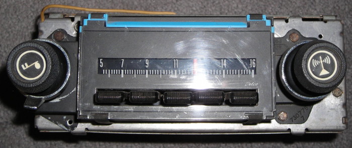
6 1⁄4" shaft spacing with 4 1⁄2" x 1 9⁄16" center opening
Some vehicles using this size radio include:
- 1963 - 1964 Chevrolet full-size cars
- 1964 - 1966 Chevrolet C/K series trucks

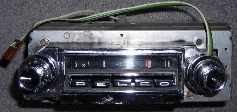
This particular example is shown with the optional front/rear speaker fader control.
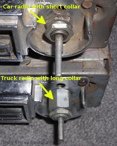
Note: Both car and truck applications feature a recessed area cast into the face plate around the RH tuning knob shaft. This area is unused on truck radios and has a fairly long mounting collar around the RH shaft that extends all the way out to the dash (where it is secured with a nut). Car radios make use of the recessed area to accommodate an optional front/rear fader control used for a rear speaker. Therefore, the car radios have a shorter mounting collar around the RH shaft. The cutout in the car dash opening has a larger hole on the RH side for the special cupped mounting washer used in conjunction with the shorter/recessed collar.
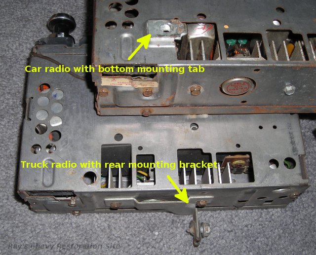
There are also some diffences in the bottom/rear mounting support on the car vs. truck radios in this year range. The car radio has provisions for a support bracket to attach to the bottom cover plate. While the truck radio uses a mounting bracket attached to the rear of the case.
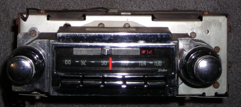
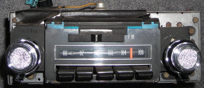
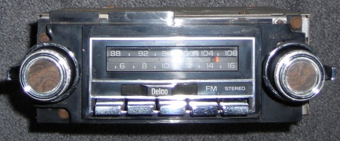
6 1⁄4" shaft spacing with 4 1⁄2" x 1 3⁄4" (or 1 13⁄16") center opening
Some vehicles using this size radio include:
- 1969 - 1976 Chevrolet Camaro
- 1969 - 1976 Chevrolet Nova
- 1969 - 1972 Chevrolet Impala/Caprice
- 1969 - 1972 Chevrolet Chevelle/Malibu/ElCamino
- 1970 - 1972 Monte Carlo
Note 1: The center portion of the faceplates on these radios are slightly larger than the dash opening. That is because they are designed to have the faceplate fitting up against the back of the dash (instead of fitting through the center opening).
Note 2: The coloring of the lens changed from green to blue sometime in the 1970 / 1971 timeframe (exact changeover date may have varied by model).
Note 3: The 1969 versions of these radios used a different electrical connector than the 1970+ ones. See the Electrical Connections and Common Wire Color Codes section for details on the wiring changes.
6 1⁄4" shaft spacing with 4 1⁄2" x 1 7⁄8" center opening
Some vehicles using this size radio include:
- 1967 - 1968 Chevrolet full-size cars
Sorry, no example photos of these radios yet.
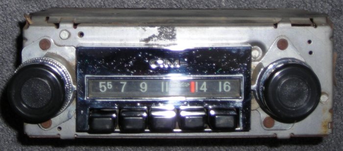
6 1⁄4" shaft spacing with 4 1⁄2" x 2 1⁄4" center opening
Some vehicles using this size radio include:
- 1960 - 1964 Chevrolet Corvair (not verified, see note)
- 1962 - 1965 Chevrolet ChevyII/Nova (not verified, see note)
- 1967 - 1972 Chevrolet/GMC C/K series trucks
- 1969 - 1972 Chevrolet K5 Blazer and 1970 - 1972 GMC K5 Jimmy
- 1971 - 1980's Chevrolet/GMC G series vans
Note: The Corvair & ChevyII/Nova pushbutton radios might have a slightly smaller face that is 2-⅛" tall. Some of the Corvair & ChevyII/Nova radios appear very similar to the truck radio pictured below except they have the word "Chevrolet" inside a bowtie logo on the face instead of "GM". And from what I have seen, the van radios look nearly identical to the truck radios except they usually have a black (instead of chrome) face.
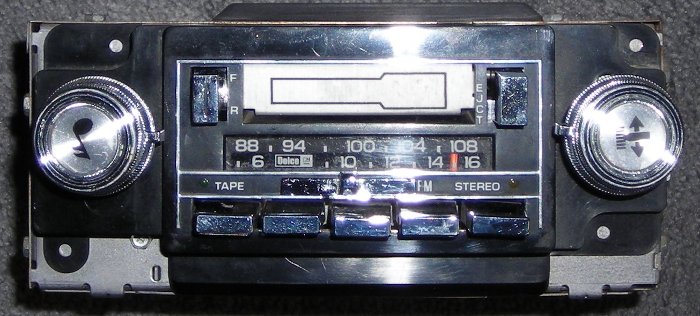
5 3⁄4" shaft spacing with 4 1⁄4" x 2" center opening
This radio size was introduced in 1973 and by the late 70's to early 80's it had become the GM corporate standard for most trucks and rear wheel drive cars. The GM service & repair literature often refers to these as Delco 2700 series units.
Some vehicles using this size radio include:
- 1973 - 1986 Chevrolet & GMC C/K series trucks, Suburbans, and K5 Blazer/Jimmy
- 1987 - 1988 Chevrolet & GMC R/V series trucks, Suburbans and Blazer/Jimmy
- 1977 - 1979 Chevrolet Nova & GM X-body cars
- 1977 - 1981 Chevrolet Camaro & Firebird
- 1977 - 1982 Chevrolet Corvette
- Many 1973 to early 80's Chevrolet / GM full & mid-size cars
Note: This list is grouping these radios according to the knob spacing and center hole dimensions only and does not take into account the wiring change that took place in 1978. See the Electrical Connections and Common Wire Color Codes section for details on the wiring changes.
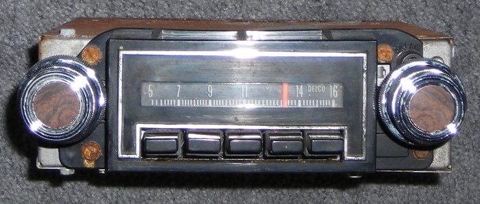

Note: The center portion of the faceplates on many of these radios is taller (and a little wider) than the actual dash opening. That is because they are designed to have the faceplate fitting up against the back of the dash (instead of fitting through the center opening).
Electrical Connections and Common Wire Color Codes
| Socket on Back of Radio | Corresponding Connector(s) | Connector Pin-out Diagram |
|---|---|---|
|
|
|
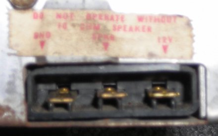
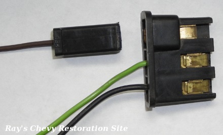
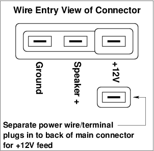
The 3 terminal radio socket shown above is used on many 1963 & newer Chevy cars and trucks with mono AM or AM/FM radios. I believe it continued to be used in cars until 1968 and pickup trucks until 1972, possibly beyond that in some applications. The 3 terminal plug that fits these radios is part of the speaker harness and uses Packard 56 series female terminals on the speaker wires. The power wire connection uses a special extension or "piggyback" terminal with a female end that plugs into the radio and a male end that accepts a single-terminal power wire connector from the vehicle. On most cars, the power wire is part of the dash harness. On most pickup trucks, the power wire is a separate wire that simply plugs into the fuse box and runs over to the radio. The dial light in these radios is powered from the car's switched +12V feed wire. The radio's internal wiring is configured to switch the dial light on & off along with the radio. On cars equipped with a rear speaker, a second sub-harness (with matching 3-terminal plugs) is jumpered in between the radio and front speaker harness. This sub-harness connects to a fader control (that slides over the RH tuner shaft) and is used to divide the radio's single speaker output between the front and rear speakers. Wire color codes for this style of radio connector varied, but the most common are:
|
||
| Socket on Back of Radio | Corresponding Connector(s) | Connector Pin-out Diagram |

|

| No diagram drawn yet |
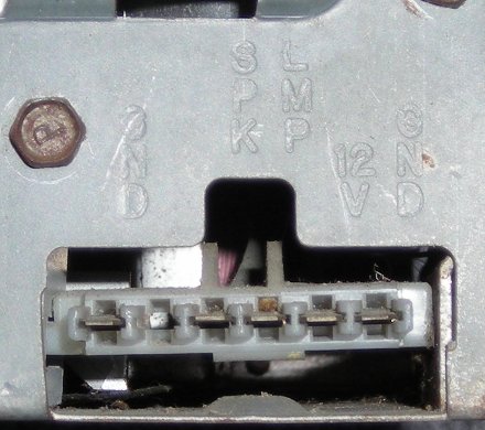
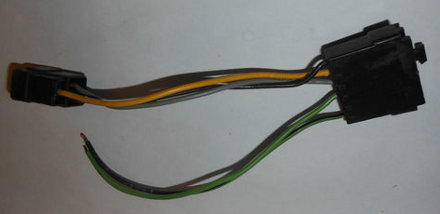
The 5 cavity radio socket & plug shown above is used in many 1969 Chevy cars. The mating plug that fits into the back of the radio is part of a speaker/jumper harness. It uses Packard 56 series female terminals on the speaker wires. The power, ground, and dial light wire connections use special extension or "piggyback" terminals with a female end that plugs into the radio and a male end that accepts the power/ground/light connector from the car's wiring harness. The particular example shown above does not contain a dial light wire. I believe the internal wiring in these radios is configured to switch the dial light on & off with the radio. On cars equipped with a rear speaker, a second sub-harness (with matching 5 cavity connectors) is jumpered in between the radio and front speaker harness. This sub-harness connects to a fader control (that slides over the RH tuner shaft) and is used to divide the radio's single speaker output between the front and rear speakers. Wire color codes for this year appear to be fairly standard but may vary with some applications:
| ||
| Socket on Back of Radio | Corresponding Connector(s) | Connector Pin-out Diagram |
|
|
|
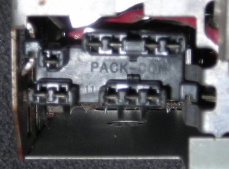
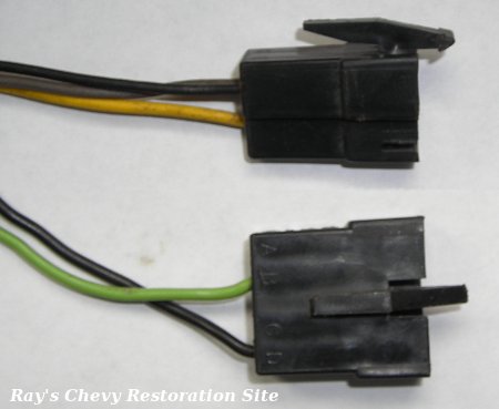
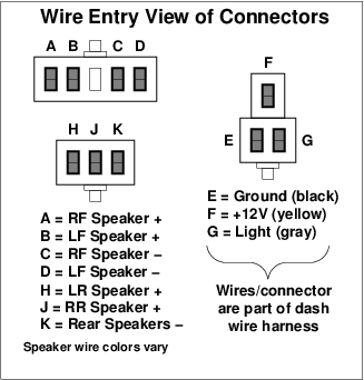
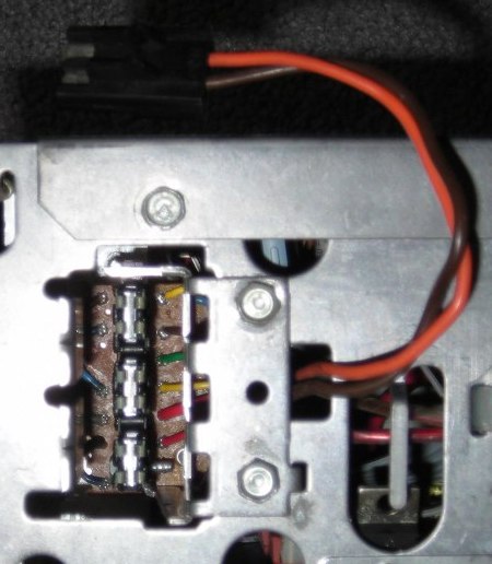
The 6 cavity radio socket & plug shown above is used on 1970 - 1976 Novas and Camaros as well as 1970 - 1972 Chevelles with mono AM or mono AM/FM radios. The mating plug that fits into the back of the radio is part of a speaker/jumper harness. It uses Pack-Con female terminals. The jumper harness also includes a 3-terminal power/light/ground connector that uses Packard 56 series terminals and plugs into a mating connector that is part of the car's dash harness. Note: The example (pictured above left) is from a radio designed to operate a single speaker. So it has an empty cavity in location "B" instead of a rear speaker + terminal. Also, the speaker/jumper harness (pictured above center) is for a single speaker application as well, and it is missing the 2-terminal connector on it's black & green wires that go to the speaker. The dial light in these radios is connected directly to the car's instrument panel lighting circuit. So the dial light turns on & off with the car's parking and/or headlights (whether the radio is on or not). And rotating the car's headlight switch knob varies the brightness of the dial light along with the instrument panel lights. Wire colors for the speakers sometimes vary, but for the most part they tend to be standardized to:
| ||
| Socket on Back of Radio | Corresponding Connector(s) | Connector Pin-out Diagram |

|

| not drawn yet |
A 9 cavity radio socket was used on the stereo version of the radios described above. This connector has 9 terminals arranged in two rows. The mating plug that fits into the back of the radio is part of a speaker/jumper harness. It uses Pack-Con female terminals. The jumper harness also includes a 3-terminal power/light/ground connector that uses Packard 56 series terminals and plugs into a mating connector that is part of the car's dash harness. For the connector on the back of the stereo: The row with 4 terminals contains:
The row with 5 terminals contains:
| ||
| Socket on Back of Radio | Corresponding Connector(s) | Connector Pin-out Diagram |
|
|
|
The 10 cavity radio socket shown above is used on many Chevy cars starting in 1971. Exceptions include 71 & 72 Chevelles, and 71 through 76 Novas & Camaros which used the 6 or 9 terminal connectors shown above. Novas & Camaros used this 10 terminal style for 1977 only. It was also used in 1973 - 1977 GM pickup trucks, Blazers/Jimmys, and Suburbans. The socket is divided into three sections, each of which accepts a plug that uses female Pack-Con terminals. The 3-terminal power/light/ground plug is part of the under-dash harness and the wire color coding on this is usually:
The 3-terminal and 4-terminal speaker plugs are part of the speaker harness(es) and the wire color coding depends on the particular radio and application. Not all terminals are present for single speaker and front/rear mono applications. The speaker harnesses on some 2-speaker stereo setups ran one speaker off the front, the other off the rear, and used 5 foot sections of 2Ω-per-foot resistance wire (10Ω total) to take the place of the other two speakers. Speaker terminals on the 4-terminal connector are:
Speaker terminals on the 3-terminal connector are:
Some 1976 & 77 stereo radios use a very similar looking 11 cavity connector (not shown). Those have a 4-terminal (instead of 3-terminal) connector for the rear speakers; giving each rear speaker it's own ground/return wire. The dial light in these radios is connected directly to the car's instrument panel lighting circuit. So the dial light turns on & off with the car's parking and/or headlights (whether the radio is on or not). And rotating the car's headlight switch knob varies the brightness of the dial light along with the instrument panel lights. Some of these radios featured a digital tuner and clock display. These will have an additional 2-wire pigtail/socket on the back with orange and brown wires that are connected as shown for the following style. |
||
| Socket on Back of Radio | Corresponding Connector (s) | Connector Pin-out Diagram |
|
|
|
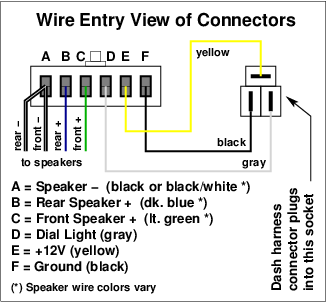
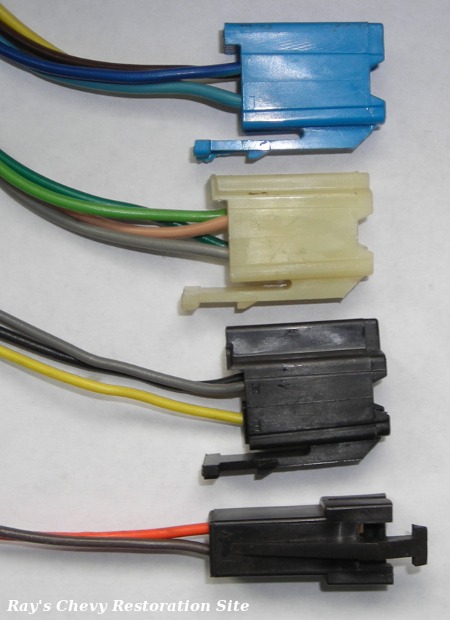
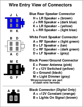
The 12 terminal socket shown above is used on nearly all GM radios/stereos/tape players from 1978 up into the early 1990's (certain models). The socket is divided into three 4 terminal sections (power, front speakers, and rear speakers). Radios with digital tuners / clocks have an additional 2 terminal connector. The wire colors on these connectors seem to be standardized to:
Not all radios with this style of connector make use of all the available connectors or terminals. For example, single speaker mono radios only have light/dark green speaker wires going to terminals A and C on the white connector and the blue rear speaker connector isn't even used at all. The dial light in these radios is connected directly to the car's instrument panel lighting circuit. So the dial light turns on & off with the car's parking and/or headlights (whether the radio is on or not). And rotating the car's headlight switch knob varies the brightness of the dial light along with the instrument panel lights. The black 2-terminal connector used on digital radios uses Pack-Con terminals and is usually on it's own sub harness. The orange wire usually plugs into the "BAT" tap point on the fuse box. And the brown wire usually plugs into the parking light circuit on the headlight switch. |
||
Speaker Information
Polarity:
Speaker terminals are often (but not always) marked with + and - symbols to denote the polarity. Connecting them backwards won't do any harm but it will cause the speaker cone to move in the opposite direction. That can cause sound cancellation issues if one speaker is wired correctly and the other is wired with reverse polarity.
On speakers where the terminals are not clearly marked, a quick check can be done using a 1.5V battery (AAA, AA, C, or D cell). Disconnect the speaker to be tested and temporarily hook it up to the battery while watching the speaker's cone. If the cone moves out then the speaker's + terminal is the one hooked to the + side of the battery. If the cone moves in then the speaker's - terminal is hooked to the + side of the battery.
The above test test (using a 1.5V battery) can also be used as a quick check for a questionable speaker. If the speaker is functional (voice coil good and cone free to move) it will emit a "click" or "pop" noise when connecting / disconnecting the battery. This test obviously won't detect a speaker with defects that can cause distorted sound, but it will let you know if the speaker is completely dead (no sound).
Grounding:
Most 60's and many early 70's Delco radios use grounded speaker systems. With these grounded speaker systems, the negative (-) speaker terminals are connected to the vehicle's metal body. And any negative speaker connections on the radio plug are internally connected to ground (the radio's metal case). This allows rear speakers in some car applications to only have a single wire running from the radio back to the speaker (and a short ground wire from the negative speaker terminal to the car body).
Delco radios from the mid/late 70's and newer have ungrounded speaker systems and will be damaged if any of the speaker wires are connected to ground. When in doubt, run all of the speaker wires back to the appropriate terminals on the radio.
Impedance:
Most transistorized Delco radios (as shown on this page) have the output transistor(s) biased to work with 8Ω to 10Ω speakers. I have read (but not confirmed) that the 1979 & newer ETR (electronically tuned receiver) Delco steros have amplifier circuits capable of driving 4Ω speakers.
Here is a good source for 8 - 10Ω speakers in the correct sizes to fit most older vehicles: S & M Electro-Tech Classic Car Speakers.
Stereo Separation:
Stereo channels are typically separated left and right. However, some vehicles have one stereo channel feeding the front speaker and the other channel feeding the rear speaker.
Other External Components & Accessories
8 Track Tape Players:
Unfortunately, I don't have a lot of information available on these, but Delco did offer factory and/or dealer installed 8 track tape players for many vehicles. Some wiring information for these can be found at: The 8 Track Repair Center -- Wiring.
Fader Controls:
Most applications with rear speakers use a fader control to split and adjust the output between the front & rear speakers. These fader controls are a specially constructed rheostat that slides over the radio's tuning shaft. The fader control assembly also includes a knob (that is styled to match the application) and wires that plug into a speaker wiring sub-harness.
Sometime around 1972, Delco started building radios with built-in fader controls. The built-in control eliminated the need for extra wiring and provided rear speaker output connections directly on the radio. The letter K near the end of the radio's Service Model Number designates a model with an integral fader control. I believe dealer installed rear speakers continued to use the external fader controls.
Convector Assemblies:
All radios covered on this page have the output transistor(s) mounted on a heatsink. Most are an integral part of the radio assembly. However, some applications (like early AM/FM receivers) did not have enough room inside the radio case so these components were mounted externally. These external heatsink / transistor assemblies were refered to as "convector assemblies" in the Delco radio literature.
A radio that uses one of these external convector assemblies will not function correctly without one. However, a missing convector assembly usually isn't a major problem. A functional replacement can often be constructed using parts salvaged from a similar vintage Delco AM radio.
Load Coils:
As with the convector assemblies, the load coils were typically an integral part of the radio assembly. But some applications (mostly Corvettes I beleive) had them mounted externally (often attached to the speaker).
Static / Noise Suppression
Factory radio installations included a number of additional components throughout the vehicle intended to reduce noise and interference. These typically included capacitors (aka. condensers) connected to the ignition coil, voltage regulator, and heater blower motor. Additional ground straps were also included with factory radio installations. And some applications added a grounding tang (to the cowl / upper firewall area) to insure a good ground connection to the hood.
Modifications and Add-Ons for FM and Auxillary Inputs
FM Converters:
Factory AM/FM radios for 60's and early 70's applications can be difficult to find (and often expensive). This is especially true for vehicles with the 6-¼" knob spacing. A quick and easy solution is to use the stock AM radio along with an AM/FM converter. These converters were manufactured/sold by a number of companies with Audiovox, Kraco, Realistic (Radio Shack), and RCA being some of the more common brands.
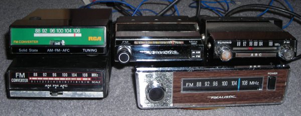
Installation of one of these converters involves unplugging the antenna lead from the vehicle's AM radio and inserting it into the socket on the back of the converter. Then plug the antenna cable from the converter into the antenna socket on the AM radio. Hook up the converter's power wire (through an inline fuse) to a +12V source that is switched on/off with the ignition. Mount the converter (usually under the dash) where it's tuning knob will be within easy reach. The mounting bracket usually provides the ground but some converters have a separate ground wire or ground through the antenna cable shield.
Operation of these converters is simply a matter of tuning the vehicle's AM radio to the converter's output frequency (typically around 1400kHz) and then using the tuning knob on the converter to select an FM station. However, one disadvantage of using an FM converter is that they typically don't offer any station preset buttons. Although, that's probably not a big deal if you usually only listen to one favorite FM station.
Auxillary Inputs:
An increasingly common modification is to add an auxillary (aux input) jack to allow a portable CD player, MP3 player, or other source to be fed into the audio amplifier stage of a stock radio.
Here are some links showing how to perform this modification (use at your own risk).
- AUX input jack for 67-72 AM radio This is written for a 67-72 GM truck AM radio but the same procedure applies to many 60's and 70's Delco mono radios.
- 73-87 Delco radio with aux. input added This one is written for 73-87 GM trucks with AM/FM stereo but applies to many other 70's and 80's Delco stereo radios.
Knobs, Mounting Hardware, and Removal / Installation Instructions
Knob Styles:
Many different knob styles were used on these radios over the years. The outer knobs (for volume and tuning) are designed to fit onto a D-shaped shaft and are generally interchangeable among all of the Delco radios covered in this guide. The inner knobs (for tone and fader) also have D-shaped openings and will also swap among most of the radios covered in this guide. However, some designs have different depth offsets to fit certain vehicle dash bezels, limiting their interchangeability. Also, applications without a fader control typically use a decorative ring (with a round hole) in place of an inner knob behind the RH tuning knob.

Mounting Hardware:
All radios covered in this guide attach to the vehicle dash with nuts behind each of the knob locations. Most use extra fine thread 7⁄16"-28 hex jam nuts (as shown at the top of the photo to the right). These can be removed with a ⅝" deep well socket. Some models may require a thin wall socket. Others use round nuts with 2 notches in them (as shown at the bottom of the photo to the right). These can be removed with a special 2 prong spanner tool (such as OPGI Part #G241122). Or, in a pinch, the tips of a pair of needle nose pliers (opened up just enough to clear the shaft) can be inserted into the nut's notches and used to turn them loose.
Some applications make use of stamped steel cup-shaped mounting adapters to take up the size difference between the holes in the dash bezel and the radio shafts. All applications have some sort of brace to support the radio case so it's not just hanging by the two nuts behind the knobs. These support braces are fairly vehicle specific and might not fit directly onto radios swapped in from other applications (like the '63-'64 car vs. '64-'66 truck radios shown earlier in this guide).
Removal & Installation Instructions
Since creating this radio information page, I have received a few emails from folks asking how to remove & install these radios or where to find instructions to do so. Unfortunately, I don't have any vehicle specific instructions, but the general procedure is usually similar for the majority of these 2-shaft style radios.
- Note: Vehicles with air conditioning have some additional under-dash ductwork that might block access to the radio. Removal of this ductwork may be nessary to gain access to the radio and provide room to remove it.
- The electrical wiring can usually be unplugged from the back of the radio by reaching up under the dash. The various designs of electrical plugs are (described here). Note that some of them have latching tabs that have to be squeezed to release them from the radio. The coaxial wire lead-in for the antenna can be unplugged by pulling it straight out of it's socket on the radio.
- The knobs generally pull straight off the shafts. However, add-on fader controls (described here) will have wires attached to the fader/knob assembly. Those wires have to be unplugged (by reaching up under the dash) and then carefully pulled out through the opening as the fader/knob assembly is slid outward off the shaft.
- With the knobs out of the way, the nuts securing the shafts to the dash can be removed. As described above in the "Mounting Hardware" section, the tool required varies depending on the style of nuts used.
- Finally, working from up under the dash, the radio can be unbolted from it's support brace(s) and carefully lowered down from under the dash. Sometimes this is a tight fit and requires tilting the radio one way or another, or possibly removing other under-dash items that might be in the way.
- Installation is the reverse of the removal procedure.
Model / Service / Reference Number Identification
GM Delco radio receivers from this era originally had a paper identification tag pasted onto the case. The location and information provided on the tag varies by year. Some of the early years had the tag on the inside cover.
Most 1968 & earlier
The Model Number on these radios can be used to identify the original application. A list of model numbers & applications can be found at: WonderBarMan.com -- Delco Model Numbers and Date Codes.
Late 1968 - 1975
The Service Model Number on these radios can be decoded as follows:
- First Digit = Model Year (8 = 1968, 9 = 1969, 0 = 1970, 1 = 1971, 2 = 1972, 3 = 1973, 4 = 1974, 5 = 1975)
- Second Digit = Car Line (1 = Chevrolet, 2 = Pontiac, 3 = Oldsmobile, 4 = Buick, 5 = Cadillac, 6 = GMC)
- Third Letter = Fisher Body Style (example: X = Nova, Omega, Ventura, Apollo)
Note: Some units are are interchangeable and/or shared with other body styles. For example, some Camaros (F-body) originally used radios with a Nova (X-body) code on the tag. - Fourth & Fifth Letters = Radio Type (PB = AM mono pushbutton, FP = AM/FM mono pushbutton, FM = AM/FM stereo pushbutton, etc.)
- Additional Letters (if present) (T = 8-track tape player (1970+), K = integral front/rear fader control (1972+))
- Final Number = Revision Number (example: 1 = 1st design)
More info can be found at: Chevelles.com -- Decoding Radio Tags.
1976 - Mid 1980's
The Service Model Number or Service Reference Number on these radios decodes much like previous years:
- First Digit = Model Year (6 = 1976, 7 = 1977, 8 = 1978, 9 = 1979, 0 = 1980, 1 = 1981, 2 = 1982, 3 = 1983, etc.)
- Second Digit = Car Line Basically the same as previous years except many have a "0" that I believe denotes a GM Corporate radio used in multiple car lines.
- Third Letter = Fisher Body Style Same as previous years. Although increased interchangeability results in more units being shared among body styles.
- Fourth & Fifth Letters = Radio Type Similar to previous years but with some additional codes to denote cassette tape players, electronically tuned receivers, etc. Unfortunately, I don't have a complete list of these codes.
- Final Number = Revision Number Same as previous years.
Late 1980's & Newer
Delco changed back to individual model numbers sometime after 1983. I do not have a list of these numbers.
Service and Repair
I have received a few emails asking if I service & repair these radios. The answer is no. While I have fixed a few for my own personal use, I'm not in the radio repair business.
Here are some links to a few companies that do automotive radio service, repair, and restoration work:
- ClassicCarRadioRestoration restores & upgrades factory radios to AM/FM, Bluetooth, USB, MP3, and more.
- JV Restorations repairs & restores 60's & 70's automotive radios and speakers.
- BC Electronics offers repair and restoration services for most Delco automotive radios.
- Antique Car Radio Repair offers repair, restoration, and conversion services 1930's through 1970's radios.
- M&R Auto Electronics offers repair service for factory automotive radios. Judging by the photos on their website, it looks like they're mostly into newer (1990's +) radios but might work on the older ones too.
Links to Additional GM Delco Radio Information & Resources
- Decoding Radio Tags from the Radio Tech Articles on Chevelles.com
- SAMS Photofacts for many GM radios can be purchased from SAMS Technical Publishing.
- Old paper copies of the SAMS Photofact AR-series (AutoRadio-series) are available from many sources including www.findatube.com.
- Ebay sellers themrgrandprix & myradios69 both offer many new and restored wiring harnesses, connectors, and other related parts for older GM Delco radios.
Radios, plugs, and accessories pictured on this page are not for sale. Pictures are for illustration purposes only. I do not offer radio repair or restoration services. Please see the Service & Repair section above if you are looking for a company to repair or restore your radio.
- Return to Ray's Restoration Site Home Page
- e-mail:ray_mcavoy@yahoo.com
- © 1998 - 2026 Raymond McAvoy. All Rights Reserved.