This page will describe the conversion of my '77 Nova from warning lights to gauges. This conversion involves replacing the regular instrument cluster with one of the optional factory gauge clusters. This conversion applies to 1977 - 1979 Novas since they all use the same style instrument panel.
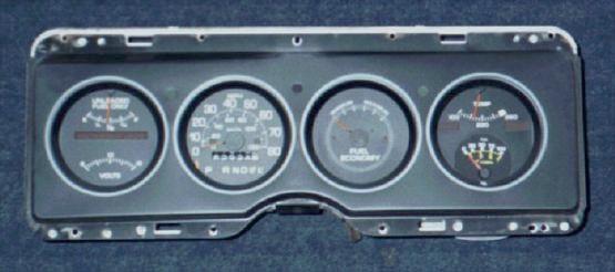
Note that there are two versions of the optional gauge cluster used in 1977-1979 Novas. The one I installed in my car (shown below) was originally available as RPO UF7 "Econominder Gauge Package" and includes a voltmeter, temperature gauge, and fuel economy (vacuum) gauge. The other version was originally available as RPO U14 "Special Instrumentation" and is basically the same cluster except with a tachometer in place of the fuel economy gauge.
Neither one of these factory Nova gauge clusters includes an oil pressure gauge so I removed the clock (which didn't work anyway) from the cluster and modified an aftermarket oil pressure gauge to fit the opening. See my Mechanical Oil Pressure Gauge Information page for details on how I used a Tee fitting to retain the original "OIL" light when I added the gauge.
Parts Required for the Conversion
Differences in the Gauge vs. Light Wiring Harnesses
The Swap Procedure
If possible, obtain and use the under-dash wiring harness from the gauge cluster donor car.
I bought my gauge cluster on eBay without the wiring so I made the following modifications:
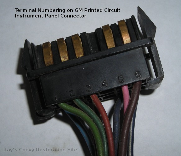
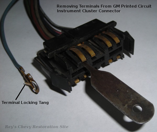
These photos show a typical GM instrument cluster connector. The one pictured is a 12-pin connector as is used in 69-76 Novas. 1977-79 Novas use a longer 18-pin connector but it still features the same terminal markings as shown in the first photo. The second photo illustrates how to remove the terminals from the plastic connector housing. Insert a small flat bladed pick (the one shown here is homemade from an old hacksaw blade) into the connector to depress the terminal locking tang. Once that tang is depressed, the terminal (and wire) should pull easily out of the wire entry side of the connector housing. Re-form the terminal locking tang by bending it back up a little before re-inserting the terminal in it's new location.
|
|
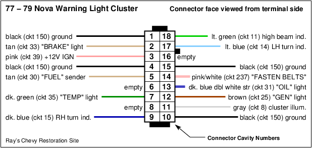
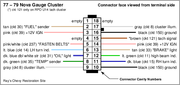
The following table lists the wires found on the cluster plug. The pin numbers correspond to the numbering on the plug as shown in the above photo and "connector face / terminal view" diagrams. The wires/terminals need to be removed from the pin# location shown in the first column (for the non-gauge cluster) and re-inserted into the locations listed in the second column. The third column lists the wire color codes. The fourth column lists the circuit number (as found on GM wiring diagrams and as shown on the "connector face / terminal view" diagrams above). The last column lists the wire's function.
| Pin # w/o gauges | Move to Pin # for gauges | Wire Color | Ckt # | Function |
|---|---|---|---|---|
| 1 | 1 | Black | 150 | Ground (not used w/gauges, see note below) |
| 2 | 13 | Tan | 33 | Brake Light |
| 3 | 3 & 14 | Pink | 39 | Fused +12V Feed from IGN Switch (see note below) |
| 4 | 16 | Black | 150 | Ground |
| 5 | 2 | Tan | 30 | Fuel Gauge Sending Unit |
| 6 | N/A | N/A | N/A | Empty slot on non-gauge connector |
| 7 | 8 | Dark Green | 35 | "TEMP" Indicator or Gauge Sending Unit |
| 8 | N/A | N/A | N/A | Empty slot on non-gauge connector |
| 9 | 11 | Dark Blue | 15 | RH Turn Signal Indicator |
| 10 | 10 | Black | 150 | Ground |
| 11 | 9 & 17 | Gray | 8 | Cluster Illumination (see note below) |
| 12 | N/A | Brown | 25 | "GEN" Indicator (not used w/gauges) |
| 13 | 7 | Dark Blue w/Dbl White Stripe | 31 | "OIL" Indicator |
| 14 | 5 | Pink w/White Stripe | 237 | Fasten Seat Belt Indicator |
| 15 | 18 | Black | 150 | Ground (not used w/gauges, see note below) |
| 16 | N/A | N/A | N/A | Empty slot on non-gauge connector |
| 17 | 6 | Light Blue | 14 | LH Turn Signal Indicator |
| 18 | 12 | Light Green | 11 | High Beam Indicator |
| Needs to be added to | 15 | Brown | 121 | Tachometer Signal |
Note: The non-gauge cluster has four ground wires, one +12V feed wire, and one cluster illumination wire. While the gauge cluster has two ground wires, two +12V feed wires, and two cluster illumination wires. I believe this was done (along with the pin re-arrangement) in order to satisfy the design constraints of the printed circuit on the back of the instrument cluster.
The two "extra" ground wires are no problem. Just leave them disconnected or place them in locations #'s 1 and 18 on the connector (those are unused on the gauge cluster). Adding the additional +12V feed and illumination wires involves salvaging some extra terminals and short sections of wire from a junk car. I took mine from an '88 Chevy Celebrity (many 70's and 80's GM vehicles use the same style of terminals). I spliced these short sections of wire w/terminals onto the existing +12V feed and illumination wires.
The SI-series internally regulated alternators used in these cars receive their field current supply from two sources. (1) Through the in-dash "GEN" light, and (2) through an internal connection to the alternator's diode trio. The current that flows through the "GEN" light is what initially energizes the field. Once the alternator is generating power, the field is "self energized" through the diode trio connnection. Since the gauge cluster lacks a "GEN" light, GM used a 10 Ohm resistance wire in the gauge harness to take the place of the light. Current to initially energize the alternator's field coils flows through this resistance wire just as it would through the "GEN" light. It is important that this be a resistance wire (or resistor) as opposed to a regular wire. Otherwise, the output of the diode trio would be connected directly to the battery (through the ignition switch) and that could damage the diode trio. In other words, the alternator's output current should be flowing through its high-current output diodes (as designed) rather than through the low-current diode trio.
To add the resistance wire (or resistor) to the non-gauge harness, start by locating the "GEN" light wire on the cluster plug. This is the brown wire originally located in slot/pin number 12. Connect the end of this wire to a 5 foot long section of 2 Ohms-per-foot resistance wire. Insulate the connection/splice with some heat shrink tubing. Next, locate the 12 gauge orange wire on the ignition switch connector. Connect the other end of the resistance wire to the same terminal as this orange wire.
Note 1: A resistor can be used in place of the factory type resistance wire. However, it needs to be a fairly high wattage resistor.
Note 2: This added resistance wire (or resistor) is not necessary if using a "1-wire" alternator. The brown ckt #25 wire can simply be left unhooked under the dash (insulating the end with electrical tape or heat shrink tubing would be a good idea though). Just be aware that you won't be able to go back to a stock type "3-wire" SI or CS alternator and have it charge correctly if ckt #25 is left unhooked.
The non-gauge cluster uses a wire connected to one of the ignition switch ground terminals to perform a key-on bulb check of the "TEMP" light. This is no longer needed with the temperature gauge. Simply locate the 20 gauge dark green wire on the ignition switch connector and remove it from it's socket in the plastic housing. Insulate the terminal with some heat shrink tubing so it won't short out on anything or snap it into a spare single-terminal plastic housing.
The temperature switch is threaded into the lower thermostat housing on L6 engines and into the driver side cylinder head (between #1 and #3 spark plugs) on small block Chevy V8 engines. The switch used with the "TEMP" light is simply an on/off switch. A variable resistance type sending unit is used with the gauge. Both have the same size 1/2" NPT threads where they screw into the engine. So swapping is simply a matter of (1) draining the engine coolant (just opening the radiator drain plug will usually get the level low enough), (2) Unscrewing the old switch, (3) Screwing in the new sending unit, and (4) re-filling the engine/radiator with coolant.
1513321 was the original GM part number for the gauge type temperature sending unit used on nearly all 1956 - 1978 (and some 79) Chevy inline-6 and V8 engines. It is discontinued and has been superseded a number of times over the years. GM is currently offering #12334869 (AC Delco #G1852) as a replacement. Other equivalent replacements include Standard Motor Products #TS-6 and Wells #TU5. The resistance ranges/specifications on these replacement sending units don't always match up to the requirements of the original gauges and may result in abnormally high gauge readings. American Autowire offers a reproduction that matches the appearance and original specifications of the original GM #1513321 sending unit.
The #1513321 and replacement sending units all have 1/2" NPT pipe threads and a "nail head" type connector. The warning light switches usually have a 1/4" flat blade type connector and may require changing the plastic terminal housing on the sending unit wire.
The cluster I bought off eBay did not include the vacuum hose and the parts car it came from was long gone. But after posting an inquiry on Steves Nova Site, Paul McCullough e-mailed me some photos and even mailed me the hose/grommet from one of his parts cars. Thanks Paul! Here is one of the photos Paul sent that shows the location of the hole in the firewall:
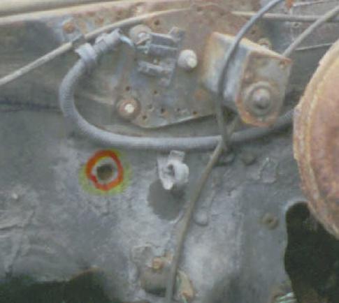
If you look closely, there will be a dimple stamped into the firewall in this location. The factory vacuum line grommet requires a hole approximately 5/8" diameter.
The original vacuum line consists of a section of 1/4" ID hose that connects to a source of manifold vacuum. I connected mine to the port at the rear of the intake manifold (I assume this was probably the factory location based on the length of the hose). The 1/4" ID hose runs through the grommet in the firewall and then connects to a plastic reducer fitting. From there, a section of 3/16" ID hose runs up to the nipple on the back of the gauge.
When installing a tachometer cluster, it will be necessary to add a wire to slot 15 of the instrument panel connector as is listed at the bottom of the above table.
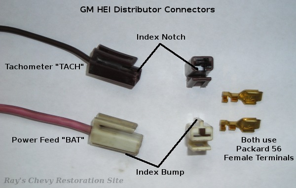
If you want to duplicate the factory wiring, use a 20 gauge brown wire. Run it through it's own grommet in the firewall (I believe the factory location is the same as the vacuum hose grommet). Crimp a female Packard 56 series terminal onto the wire and snap it into a brown plastic housing as shown in the above photo. It will then plug right into the "TACH" terminal on the HEI distributor cap. The index notches and bumps on the factory terminal housings prevent them from accidentally being inserted into the wrong terminal on the distributor.